Honeywell Thermostat Wiring Diagram And Color Codes
As the world has moved from the dark ages to modern times, humans have brought forward hundreds of unique inventions to make life easier.
Right now, you can use your smartphone to track deliveries, order food and cabs, and look at a live FA Cup match final happening in Wembley, no matter where you are situated.
Air Conditioners and HVACs are inventions that strive to make our lives comfortable and perfect. But did you know there’s so much more to those gadgets than what meets the eye?
As a result, I decided to step outside of my comfort zone today to explain a Honeywell Thermostat’s wiring and colour codes to you.
This post will provide a full rundown of all potential Honeywell Thermostat Wires, wiring combinations, and colour codes so you can repair minor HVAC issues without needing to contact an electrician.
Without further ado, let us begin.
Honeywell Thermostat: Understanding the device
The Honeywell Thermostats are the most common type of thermostat you can see worldwide. They might now be as flashy and futuristic as the Nest Thermostats, but they have a specific industrial look that gives a perfect retro vibe.
Available under numerous configurations, the Honeywell Thermostats have all the basic functions you can expect from an HVAC Controller. Different models offered by the company have different sets of button layouts and wiring configurations that you can use to maximize comfort.
A Honeywell Thermostat consists of two parts.
The Outer Shell
Usually made of reinforced plastic(which you normally see on budget smartphones and telephones), the outer layer consists of a screen with an LCD and buttons to control the HVAC.
Since Honeywell offers numerous models of Thermostats, the button layout of each model is slightly different from the others.
The Inner Layer
It consists of various electrical circuits that transmit data in the form of electric pulses to the base, with various connectors and wires attached to it.
These wires and connectors then operate each component, like heating and cooling.

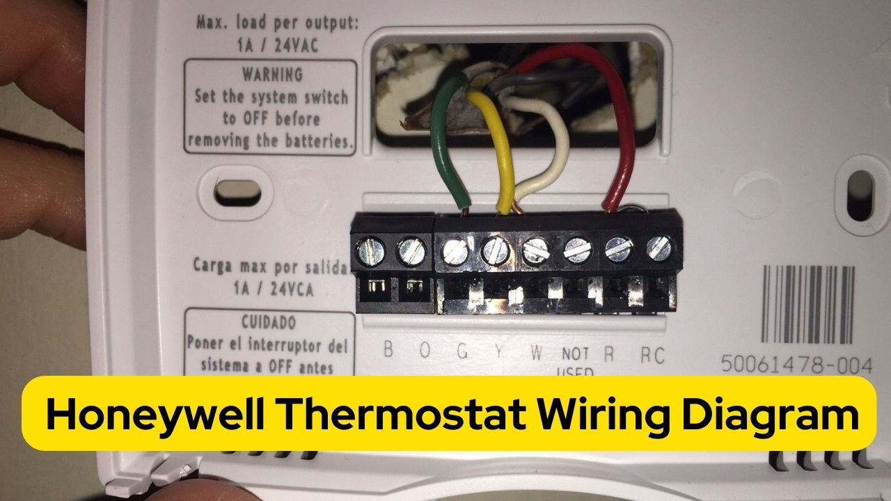
Honeywell Thermostat: Wiring Diagram and Color Codes
The Honeywell Thermostat includes five separate wires that regulate each little HVAC component, just like a power outlet has live, neutral, and earthing connectors.
These colours and functionalities can differentiate each wire:
RED – 24 Volt LIVE-Wire
As its name implies, this wire transfers power control from the Honeywell Thermostat to each heating and cooling unit in the system.
The arrangement is powered via the RED, a live terminal connected directly to the AC Power circuit.
This often connects to the Thermostat’s RC or RH terminal. Since it is frequently utilized and helps power cooling and heating agents simultaneously, I favour the RH terminal cus.
YELLOW – Cooling Wire
The Yellow wire manages the setup’s air conditioning system.
It is connected to the Compressor and centralized air conditioning grid, which sends cold air through the vents to every building room.
WHITE – Heating Wire
The system’s heaters, burners, and boilers are all under the direction of the White wire. The furnace or gas outlet, which generates hot air for the HVAC, is directly powered by it.
GREEN – Fan Wire
Control the setup’s fans with this wire. Although the heater and air conditioner will produce hot and cold air, the fans push the air out of the vents.
The Green wire controls the fan relay feature, which only activates the fans and leaves the AC or furnace off to remove moisture and humidity from space.
Occasionally, you may even use this wire to cool down rooms during a monsoon when the humidity is high, but the temperatures are much lower, saving you money and effort.
BLUE/ BLACK – Common Wire – C Wire
The C wire is a very recent addition to the setup. Most Honeywell Thermostats will not have this wire.
This wire is crucial because it provides direct power to the Honeywell battery, which works with your home’s WiFi that can help you control the HVAC remotely.

What kind of wiring and colour codes should I use for my Honeywell Thermostat?
Your wiring setup depends upon your house and the climate of your place.
For most people, the wire colour system of R-Y-G-W will do the trick.
If you own a large house with multiple rooms or a massive apartment complex, then the 5-wire setup is best for you. Yes, it could be a little costly, but it is the best option in the long run.
People who live in hot and humid climates where the temperature never drops below 15 degrees Celsius. The R-Y-G setup will be best. Whereas those who reside in colder regions where require heating. You should choose the R-W-G configuration.
The use of the C-Wire depends from person to person. The C-Wire will serve no purpose if you live in a building with little chance of a load-shedding or blackout.
Honeywell Thermostat Compatibility
Before you install a Honeywell Thermostat for your home, here’s a list of a few compatibility checks you should perform.
Input Voltage
The Honeywell Thermostat uses the basic 24 V input as power source. If your home has a lower voltage than the prescribed unit, then the Thermostat will not work properly.
Only Low Voltage systems(24 V) are compatible with Honeywell Home/Resideo. Here are some indicators that your home may have a low-voltage system:
- You have central air conditioning, a heat pump, a boiler, or a split system in your home.
- The floors of your rooms are lined with heating vents in your house. Your furnace is located somewhere (in the basement, garage, bathroom, etc.).
- A single thermostat change affects several rooms.
Fuel
Honeywell Thermostats work with electricity, natural gas, and oil, among other frequently used fuels.
Wiring Setup
The Honeywell Thermostat needs a specific set of wires to function properly. Visit the Honeywell Wiring compatibility website and see if the Thermostat’s wiring is optimal.
If you need help, you can contact customer service to get help.
How to install a Honeywell Thermostat with an HVAC?
1. Verify system compatibility
Before opening the Honeywell Thermostat box, cross-reference all the wires attached to the current Thermostat with a list of potential connectors.
The Honeywell Wiring compatibility website can help you with this.
2. Check the HVAC system
Test the heating, cooling, fan, and other system capabilities with the current Thermostat before installing the Honeywell thermostat.
3. Turn off the power to the HVAC system.
4. Take out the outdated Thermostat and patch up the holes and serrations it left in the wall.
5. Install the device
Using the screws(provided inside the box) and a screwdriver, install the device on the outlet and connect the wires carefully by following the wiring setup from Honeywell’s Wiring compatibility website.
6. To ensure the installation was done correctly, test the Thermostat’s cooling and heating features.
7. If everything is okay, finally connect the Thermostat to the local WiFi so you can control it remotely.
How to wire a 24v transformer to a Honeywell Thermostat?
To wire a 24v transformer to a Honeywell Thermostat:
- First, use a razor to cut the ends of the R-wire, often referred to as the power wire, exposing the bare copper. A half-inch-wide incision would be sufficient.
- Ensure that the HVAC system is turned off.
- Both the RC and RH terminals on the 24-volt transformer wire can be used as the R terminal. People now like the RH terminal.
- Using a tester, screw the wire into the RH terminal. Use a special screwdriver; regular screwdrivers can shock you by acting as an inductor.
- Turn the power back on at the end and see whether the Thermostat lights up this time. If not, you can swap the RH and RC terminals and try again.
If it still doesn’t work, get in touch with customer service immediately.